|
FAQ—Page 1 |
|
GENERAL
What is the best way to mount a Circuitron circuit board? All of our 5000 series boards have a common 3” height and are designed to snap into a section of our Printed Circuit Mounting Track (800-9506). You may also mount the board by drilling a small hole in the corner pads—2 diagonal corners should be adequate (be careful not to drill the whole pad away, especially if it is connected to a trace) and use small screws and standoffs or (preferred, to keep from damaging the board) use small pads of double faced foam tape on each corner (may take two layers) and just stick the board in place under your layout. A small dab of RTV Silicone Caulk touching the board and bridging the tape will make it permanent but easily removed by slicing through the caulk with a razor knife.
How do I make connections to the terminals on my circuit board? The terminals on all Circuitron printed circuit boards are industry standard male quick disconnects. They measure 0.110” x 0.032”. If you choose to use mating female quick disconnects that would simply crimp on your wires, be certain you get the .032” thickness. These are sold by Circuitron and other industrial electronic suppliers. CAUTION: They are also available in a thinner version which will not fit our boards and may cause damage or break off terminals. Most modelers will just tack solder their leads to the terminals. Our terminals are tin plated and solder very easily. It is not even necessary to put the wire through the hole in the terminal. Use a good quality 60% tin, 40% lead, rosin core electronics solder and a small soldering pencil. Do not use liquid or paste flux. It should not be necessary and might remain corrosive. Do not use too much heat and do not wiggle the connection until completely cooled. Can I use the output from a power pack to power Circuitron boards? Possibly, but unless you know the actual voltage output (NOT the specification plate rating!), you will be taking a chance. Many modern power packs have ratings that are much below what the pack puts out without a load. For instance, many MRC power packs are now designed to power all sizes of model trains up through G scale. The accessory terminals on these packs will typically put out 20-23 volts, substantially above the maximum rating of most Circuitron products. And the DC track outputs will usually be a pulsing DC waveform good for controlling locomotives at low speed but not a great choice for electronics. Where can I get a good power supply for Circuitron electronics? Circuitron manufactures AC-DC converters and regulators that can be used with the output of conventional power packs. However, these are rated for a maximum input of 18 volts AC or DC. A small AC-DC wall plug adapter such as would be provided with a telephone answering machine or other household device is a good choice for a small number of circuits. Look for one rated 12 volts DC on its nameplate with a current capacity of 500 ma or more. This would be adequate for 3-8 circuit boards. There are also regulated switching power supplies available on-line from a number of sources. These are typically very efficient units and are fully regulated to lock the voltage at 12 volts DC, ideal for most of our circuits. The desktop style is a small black “brick” with a line cord coming out of one end and a device cord coming from the other end. These are often found as the power supplies of laptop computers, game consoles, etc. They will typically be rated at 12 volts DC output with a current rating of 2-5 amps (2,000-5,000 ma.) A couple good sources for these on-line are Jameco (www.jameco.com) and Marlin P. Jones & Associates. (www.MPJA.com). Just search their sites for: Desktop switching power supply
DETECTION CIRCUITS
I try adjusting. Why won’t my circuit board indicator LEDs turn ON/OFF? When an indicator LED stays constantly ON regardless of how you turn the sensitivity adjustment, it may indicate that you have an open circuit in the Opto-Sensor wiring. This could be due to a bad solder connection or a broken wire lead. If you have used clip leads for testing purposes, try replacing them as they often go bad over time. If an indicator LED is OFF regardless of the sensitivity control position, this may indicate that the wiring to the Opto-Sensor is shorted. Check for bare wires touching, especially out at the sensor itself. Also check to make sure you didn’t drive a staple through the wires going out to the sensor. If you have a multimeter, you can test your wiring by removing the wire from the sensor terminal (S1, S2, SA, etc.). You may leave the wire attached to SD. Now set your meter on OHMS and clip one meter lead onto the SD terminal and the other lead onto the wire you just removed from the sensor terminal. In this way you are measuring the resistance of the entire Opto-Sensor circuit from SD out through your wiring to the Opto-Sensor and then back through your wiring to the board connection point. You should read some finite resistance on your meter. It should not be zero ohms nor should it be infinite ohms. If you get a reading (and the value WILL depend on your room lighting), try covering the Opto-Sensor and your meter reading should jump up scale by a factor of 5-10 times.
What is the maximum load I can apply to my detection circuit OUT terminal? All Circuitron Detection Circuit outputs can control a maximum of 250 ma. of DC current. The exception here is if you have purchased a Heavy Duty circuit. It will be clearly labeled HD and has a 500 ma. current capacity on its output(s). If you need to control more, you will need to connect a small relay to the output terminal. The relay should have a protection diode across its coil as explained in our instruction sheet.
Grade Crossing Detectors Can I use the DT-1 and DT-2 Bi-Directional detectors with DCC? Yes, but with some limitations. These boards were designed for DC track power and use the track polarity to set the detector’s action. DCC does not have a polarity. They can be used and maintain full functionality by adding a “Dispatcher’s” switch to your control panel. Download the instructions for more information or go to this page for further explanation. DT-1 Instructions DT-2 Instructions
Block Detectors Is Optical or Current Sensing detection best? There is no “best”. It depends upon your operations and needs. Optical is the easiest to install in existing trackage and requires no modifications to the locomotives or rolling stock. It does require that your room lighting be fairly constant. You cannot change from daylight to simulated night running without having to re-adjust and no single setting will work for both. Current sensing will work in varied lighting, but will only detect powered locomotives and rolling stock with lighting installed. All other pieces of rolling stock you wish to detect will have to have metal wheelsets installed with resistors wired across the wheelset insulator.
FLASHER CIRCUITS
REVERSE CIRCUITS How can I add a stop and delay to the end reversing points on my AR-1? A Circuitron Time Delay Circuit, TD-1 and a Rolling Stock Detector, DT-4 can be used to provide a stop and delay function. However the cost of these two circuits will be more than purchasing a new AR-2 Reverse Circuit which has the delay function built in.
TURNOUT CONTROL CIRCUITS Why does my TC-1 or TC-2 not have enough power to throw my switch machine? The TC-1 and TC-2 have a capacitor discharge section that is powered from the input terminals. To achieve maximum power stored in this capacitor, the circuits should be powered from an unfiltered and unregulated power source. This could be the accessory terminals of a suitable power pack or a simple AC transformer. Higher input voltages will result in more power. For maximum output, choose a supply rated 17-18 volts (either AC or unfiltered DC).
THE TORTOISE™ and SMAIL™ SLOW MOTION SWITCH MACHINE What is the current rating of the TORTOISE’s™ internal switches? The two internal SPDT switches built into the TORTOISE™ and SMAIL™ are rated to SWITCH one amp loads. However, these switches will CARRY 4-5 amps without problem. Since they are used primarily for static frog or siding power and are not actually switching the locomotive load, no contact arcing will occur and the one amp rating is not an issue. They are safe to use with most DCC systems as the electronic over-current protection of the DCC booster will shut down the booster in case of a short before the TORTOISE switches will fail. How do I make connections to the TORTOISE™ circuit board? Most modelers will simply solder wire leads onto the pads on the TORTOISE circuit board. It is not necessary to put the wire through the hole. Because of the very low current requirements of the TORTOISE™, light gauge wire such as 22 or 24 ga. will work well. Use a low wattage pencil iron and 60% tin, 40% lead rosin core electronics grade solder (available from Jameco.com). It is also possible to use a bare printed circuit board edge connector to provide simple push on connection to the TORTOISE™. It will still be necessary to solder your wires to the edge connector but this may be able to be done on the bench rather than over your head under the layout. Edge connectors are available on line from a number of model railroad suppliers and also from larger electronic supply houses. More information is available here in an Application Note. See our new ZipZ™ solderless connection system on the TORTOISE™ accessories page. |
|
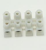
At Progressive Model Design, Circuitron’s custom model building division, we like to use a 12”-18” whip of CAT-5 communication cable. This cable is readily available at home centers and electric supply houses. The eight 24 ga. Solid wires are color coded in the cable. We fan out the wires at both ends, strip them all, and lay the one end on the traces of the TORTOISE™, using the same color code order for each one. We then tack solder them to the traces on the TORTOISE™ on the bench. We locate and mount an eight (or more) position “Euro-Style” barrier terminal block (like that shown to the right) within 12 inches of the mounted TORTOISE™ on the underside of the layout, install the machine as usual and connect the 8 wires to the terminal block. Then our layout wiring is brought into the block from the other side. This method costs less and is more easily modified than using an edge connector. |
|
Can I use pushbuttons with the TORTOISE™? We do not recommend it. The TORTOISE™ is a stall motor design. This means it is designed to be powered continuously. Removing power as would happen with a momentary pushbutton will allow the gear train to “relax”, possibly reducing the tension on the points. In a worst case scenario, you would hold the pushbutton down for the required 3 second throw. But if you let up on the pushbutton just a moment too early, the TORTOISE™ would “free-wheel” with no power applied and the inertia of the entire gear train and motor armature would be applied to the output arm. This might cause the arm to rebound off of the case stop just a bit and could potentially pull the points back open just a bit. This could cause derailments. Use continuous on switches such as toggles, not momentary. Do I need to use a separate resistor with my panel LEDs and the TORTOISE™? If you are wiring LEDs directly in series with the TORTOISE motor, a separate resistor is not necessary and should NOT be used. The stall current of the TORTOISE is around 16-17 ma and this is an ideal operating current for most all LEDs. Adding a resistor will only slow the TORTOISE motor down and is not necessary or desired. DO NOT USE AN ADDITIONAL RESISTOR. Application Note showing a diagram: AN-6000-07 How do I control a TORTOISE™ from multiple locations or control panels? Because the TORTOISE™ requires constant power to keep it stalled, controlling it from multiple locations is a bit more difficult than older style twin-coil machines. One way to do this if you are using DPDT panel switches is to “daisy chain” them. That is, take the two output leads from the first panel toggle and run them over to the second panel where they then become the INPUT leads for THAT toggle. There is no limit to the number of panel toggles you can “daisy chain” this way. The down side of this method is that the panel toggle position of the bat handle means nothing. Because flipping ANY of the switches in the chain reverses the polarity to the TORTOISE™, handle position is meaningless. You can wire indicator LEDs back to the panels to help in this situation.
|